| 1. |
The rear glass defogger switch inputs can be
checked using the GDS. |
| 2. |
To check the input value of rear glass
defogger switch, select option "Body Control
Module". |
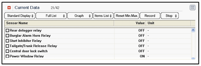
| 3. |
To consult the present input/output value of
BCM, "Current DATA". It provides information of BCM input/output
conditions of smart junction box.
|
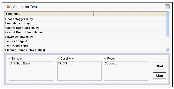
| 4. |
To check the input value of rear glass
defogger switch in force mode, select option "Actuation Test of
smart junction box".
|
| 1. |
Disconnect the negative(-) battery
terminal. |
| 2. |
Remove the center fascia panel assembly
(A).
(Refer to the Body group - "Crash
pad")
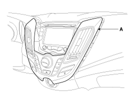
|
| 3. |
Remove the center fascia panel connector
(A).
|
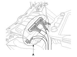
| 4. |
Remove the heater and air corditioner
controller (A), after loosening the screw (4EA).
|
| 1. |
Install the heater and air conditioner
controller to the center fascia
panel. |
| 2. |
Install the center fascia panel
assembly. | |