Front Door Lock Actuator Inspection
| 1. |
Remove the front door trim.
(Refer to the BD group - "Front
door") |
| 2. |
Remove the front door
module. |
| 3. |
Disconnect the 7P connector from the
actuator.
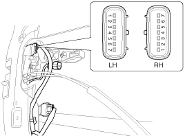
|
| 4. |
Check actuator operation by connecting power
and ground according to the table. To prevent damage to the
actuator, apply battery voltage only momentarily.
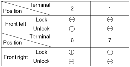
|
Rear Door Lock Actuator Inspection
| 1. |
Remove the rear door trim.
(Refer to the BD group - "Rear
door") |
| 2. |
Remove the rear door
module. |
| 3. |
Disconnect the 7P connector from the
actuator.
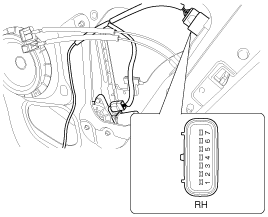
|
| 4. |
Check actuator operation by connecting power
and ground according to the table. To prevent damage to the
actuator, apply battery voltage only momentarily.

|
Tailgate Release Actuator Inspection
| 1. |
Remove the tailgate trim panel.
(Refer to the BD group -
"Tailgate") |
| 2. |
Disconnect the 4P connector from the
actuator.
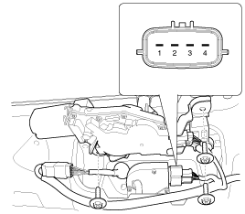
|
| 3. |
Check actuator operation by connecting power
and ground according to the table. To prevent damage to the
actuator, apply battery voltage only momentarily.

|
Front Door Lock Switch Inspection
| 1. |
Remove the front door trim panel.
(Refer to the BD group - "Front
door") |
| 2. |
Remove the front door
module. |
| 3. |
Disconnect the 7P connector from the
actuator.

|
| 4. |
Check for continuity between the terminals in
each switch position when inserting the key into the door according
to the table.
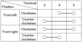

|
Rear Door Lock Switch Inspection
| 1. |
Remove the rear door trim panel.
(Refer to the BD group - "Rear
door") |
| 2. |
Remove the rear door
module. |
| 3. |
Disconnect the 7P connector from the
actuator.

|
| 4. |
Check for continuity between the terminals in
each switch position according to the table.

|
Tailgate Open Switch Inspection
| 1. |
Remove the tailgate trim.
(Refer to the BD group -
"Tailgate") |
| 2. |
Disconnect the 4P connector from the
actuator.

|
| 3. |
Check for continuity between the terminals in
each switch position according to the table.

|
Door Switch Inspection
Remove the door switch
and check for continuity between the terminals.
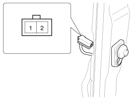

Hood Switch Inspection
| 1. |
Disconnect the connector from the hood switch
(A).
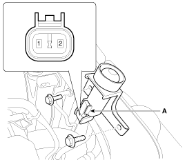
|
| 2. |
Check for continuity between the terminals and
ground according to the table.

|
Burglar Horn Inspection
| 1. |
Remove the burglar horn (A) after removing 1
bolt and disconnect the 2P connector from the burglar
horn.
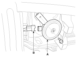
|
| 2. |
Test the burglar horn by connecting battery
power to the terminal 1 and ground the terminal
2. |
| 3. |
The burglar horn should make a sound. If the
burglar horn fails to make a sound replace
it. |