| 1. |
Disconnect the negative (-) battery
terminal. |
| 2. |
Remove the crash pad lower panel. (Refer to
the BD group - "Crash pad") |
| 3. |
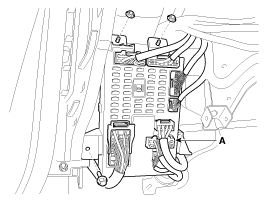
Disconnect the IPM connectors, loosening the
nut (2EA) and the bolt (1EA), then remove the IPM.

|
| 4. |
The installation is the reverse order of
removal. |
IPM Diagnosis with GDS
| 1. |
It will be able to diagnose defects of IPM
with GDS quickly. GDS can operates actuator manually, input/output
value monitoring and self
diagnosis. |
| 2. |
Select model and
"IPM". |
| 3. |
Select the module to
check. |
| 4. |
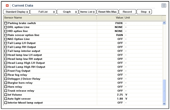
Select "Input/output monitoring", if you will
check current data of body network system. It provides input/output
status of each module.

|
| 5. |
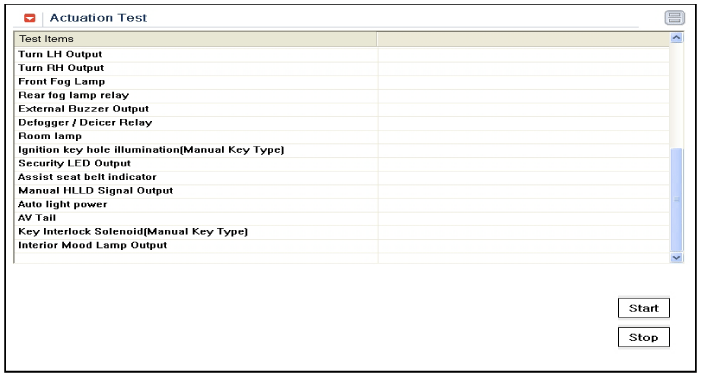
If you will check each module data operation
manually, select "Actuation test".

|
| 6. |
To check the DTC of the each module, select
"DIAGNOSTIC TROUBLE CODES".

|
| 7. |
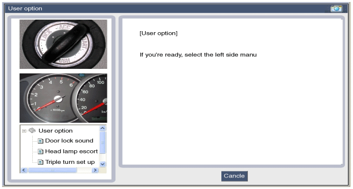
If you want to change user option, select
“user option”.

| |