| 1. |
Disconnect the battery negative cable from the
battery and then wait for at least 30
seconds. |
| 2. |
Turn the steering wheel so that the front
wheels can face straight ahead. |
| 3. |
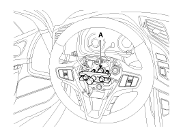
Rmove the airbag module.
3-a. Loosen the bolts (A).


3-b. Disconnet the horn
connecter.

|
| 4. |
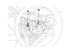
Loosen the lock nut (A), disconnect the
connector (B) and then remove the steering wheel by using
SST(09561-11001).
Tightening
torque :
39.2 ~ 49.0N.m(4.0 ~ 5.0kgf.m, 28.9 ~
36.2lb-ft)
|
|
Do not hammer on the steering wheel to
remove it; it may damage the steering
column. | |
| 5. |
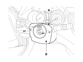
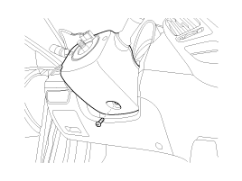
Loosen the screw and then remove the steering
column upper (A) and lower shroud (B).
|
| 6. |
Disconnect the connector and then remove the
clock spring (A).
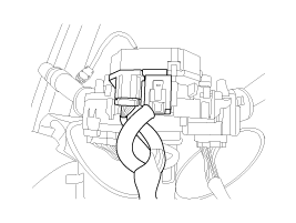
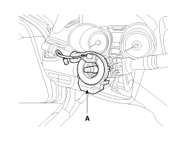
|
• When assembling set the center
position by setting the marks between the clock spring and the
cover into line. Make an array the mark (▶◀) by turning the
clock spring clockwise to the stop and then 2.0 revolutions
counterclockwise. | |
| 7. |
Remove the multifunction switches
(A).
7-a. Disconnet the connector.
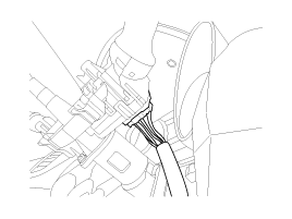
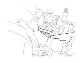
7-b. Loosen the screw.

|
| 8. |
Remove the crash pad side cover and lower
crash panel (A).
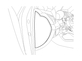
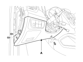
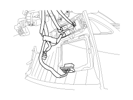
|
| 9. |
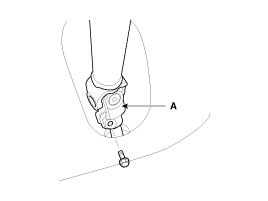
Loosen the bolt (A) and then disconnect the
universal joint assembly from the pinion of the steering gear
box.
Tightening
torque :
32.4 ~ 37.3N.m(3.3 ~ 3.8kgf.m, 23.9 ~
27.5lb-ft)
|
| •
|
Lock the steering wheel in the
straight ahead position to prevent the damage of the
clock spring inner cable when you handle the steering
wheel. |
| •
|
Must be replaced with new bolts
when assembling. (SEAL-LOCK has been
processed)
SEAL-LOCK Specifications: MS721-39
"TYPE-D" Product: ND industries
1193S | | |
| 10. |
Disconnect all connectors connected the
steering column & EPS unit
assembly. |
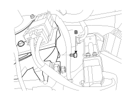
| 11. |
Remove the steering column & EPS unit
assembly by loosening the mounting bolt (B) and nuts
(A).
Tightening
torque :
Nut : 12.7 ~ 17.7N.m(1.3 ~ 1.8kgf.m, 9.4
~ 13.0lb-ft)
Bolt : 44.1 ~ 49.0N.m(4.5 ~ 5.0kgf.m,
32.5 ~ 36.2lb-ft)
|

|
| 12. |
Installation is the reverse of the
removal.
|
You must be EPS type recognition and ASP
calibration when after mounting.
(Refer to ST group - E.P.S/repair
procedures) | |
Key lock assembly
| 1. |
Make a groove on the head of special bolts (A)
by a punch.

|
| 2. |
Loosen the special bolt using a screw driver
and then remove the key lock assembly from the steering column
assembly. |
| 3. |
Reassembly is the reverse of the
disassembly. |
Universal joint assembly
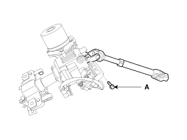
| 1. |
Loosen the bolt (A) and then disconnect the
universal joint assembly from the steering column
assembly.
Tightening
torque :
53.9 ~ 63.7N.m(5.5 ~ 6.5kgf.m, 39.8 ~
47.0lb-ft)
|
|
| 2. |
Reassembly is the reverse of the
disassembly. |
| 1. |
Check the steering column for damage and
deformation. |
| 2. |
Check the steering column for damage and
deformation. |
| 3. |
Check the join bearing for damage and
wear. |
| 4. |
Check the tilt bracket for damage and
cracks. |
| 5. |
Check the key lock assembly for proper
operation and replace it if
necessary. | |