| 1. |
Disconnect the battery negative cable and wait
for at least three minutes before beginning
work. |
| 2. |
Turn the steering wheel so that the front
wheels can face straight ahead. |
| 3. |
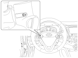
Remove the driver airbag module mounting bolts
(2EA).
|
| 4. |
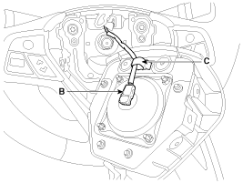
Remove the wiring fixing clip (C), and then
release the connector locking pin to disconnect the driver airbag
module connector (B).
|
The removed airbag module should be
stored in aclean, dry place with the pad cover facing
up. | |
| 5. |
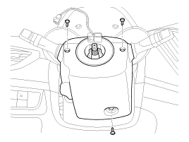
Remove the steering wheel and steering wheel
column shroud. (Refer to the Steering System group - "Steering
Column and Shaft")
|
| 6. |
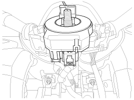
Disconnect the clock spring connector, then
remove the clock spring.
|
If any improper parts
are found during the following inspection, replace the airbag module with
a new one.
|
Never attempt to measure the circuit
resistance of the airbag module (squib) even if you are using the
specified tester. If the circuit resistance is measured with a
tester, accidental airbag deployment will result in serious personal
injury.
|
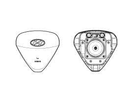
| 1. |
Check pad cover for dents, cracks or
deformities. |
| 2. |
Check the airbag module for denting, cracking
or deformation. |
| 3. |
Check hooks and connectors for damage,
terminals for deformities, and harness for
binds. |
| 4. |
Check airbag inflator case for dents, cracks
or deformities.
|
| 5. |
Install the airbag module to the steering
wheel to check for fit or alignment with the
wheel. |
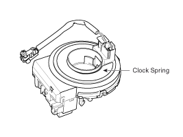
Clock Spring
| 1. |
If, as a result of the following checks, even
one abnormal point is discovered, replace the clock spring with a
new one. |
| 2. |
Check connectors and protective tube for
damage, and terminals for deformities.
|
| 1. |
Remove the ignition key from the
vehicle. |
| 2. |
Disconnect the battery negative cable from
battery and wait for at least three minutes before beginning
work. |
| 3. |
Connect the clock spring harness connector to
the clock spring. |
| 4. |
Install the steering column
shroud. |
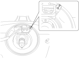
| 5. |
Set the center position by setting the marks
between the clock spring and the cover into line. Make an array the
mark (▶◀) by turning the clock spring clockwise to the stop and then
3.0 revolutions counterclockwise.
|
| 6. |
Install the steering wheel. (Refer to the
Steering System group- Steering Column and
Shaft) |
| 7. |
Connect the driver airbag (DAB) module
connector, and then install the driver airbag (DAB) module on the
steering wheel. |
| 8. |
Secure driver airbag (DAB) with the new
mounting bolts.
Tightening
torque:
7.8 ~ 10.8 N.m (0.8 ~ 1.1 kgf.m, 5.8 ~
8.0 lb-ft)
| |
| 9. |
Connect the battery negative
cable. |
| 10. |
After installing the airbag, confirm proper
system operation:
| A. |
Turn the ignition switch ON; the SRS
indicator light should be turned on for about six seconds and
then go off. |
| B. |
Make sure horn button
works. | |