| 1. |
Loosen the wheel nuts slightly.
Raise the vehicle, and make sure it is
securely supported. |
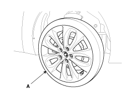
| 2. |
Remove the front wheel and tire (A) from front
hub .
Tightening
torque:
88.2 ~ 107.8 N.m (9.0 ~ 11.0 kgf.m, 65.0
~ 79.5 lb-ft)
|
|
Be careful not to damage to the hub
bolts when removing the front wheel and tire
(A). | |
| 3. |
Remove the brake caliper mounting bolts , and
then hold the brake caliper assembly (A) with wire.
Tightening
torque:
78.4 ~ 98.0 N.m (8.0 ~ 10.0 kgf.m, 57.8
~ 72.3 lb-ft)
|
|
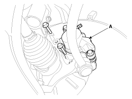
| 4. |
Remove the wheel speed sensor
(A).
Tightening
torque:
7.8 ~ 11.8 N.m (0.8 ~ 1.2 kgf.m, 5.8 ~
8.7 lb-ft)
|
|
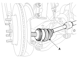
| 5. |
Remove driveshaft caulking nut (A) from the
front hub under applying the brake.
Tightening
torque:
196.1 ~ 274.5 N.m (20.0 ~ 28.0 kgf.m,
144.6 ~ 202.5 lb-ft)
|
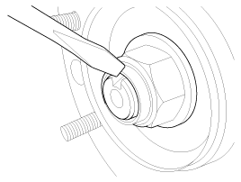
| -
|
The driveshaft lock nut should be
replaced with new ones. |
| -
|
After installation driveshaft lock
nut, stake the lock nut using a chisel and hammer as
shown in the illustration
below. | |
|
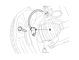
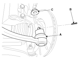
| 6. |
Remove the tie rod end ball joint (A) from the
knuckle.
| (1) |
Remove the split pin
(B). |
| (2) |
Remove the castle nut
(C). |
| (3) |
Use the SST
(09568-3400) |
Tightening
torque:
23.5 ~ 33.3 N.m (2.4 ~ 3.4 kgf.m, 19.4 ~
24.5 lb-ft)
|
|
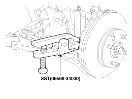
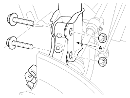
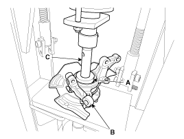
| 7. |
Remove the lower arm (A) from the knuckle by
using SST (09568-34000)
Tightening
torque:
98.5 ~ 88.3 N.m (8.0 ~ 9.0 kgf.m, 57.9 ~
65.1 lb-ft)
|
|
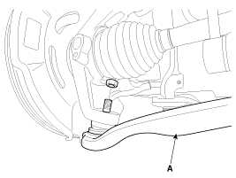
| 8. |
Disconnect the driveshaft (A) from the front
hub assembly.
|
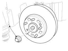
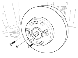
| 9. |
Remove the disc (A) by loosening the
screw.
Tightening
torque:
4.9 ~ 5.8 N.m (0.5 ~ 0.6 kgf.m, 3.6 ~
4.3 lb-ft)
|
|
| 10. |
Loosen the strut mounting bolts and then
remove the knuckle assembly (A).
Tightening
torque:
137.3 ~ 156.9 N.m (14.0 ~ 16.0 kgf.m,
101.3 ~ 115.7 lb-ft)
|
|
| 11. |
Install in the reverse order of
removal. |
| 1. |
Remove the snap ring (A).
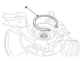
|
| 2. |
Remove the hub assembly from the knuckle
assembly.
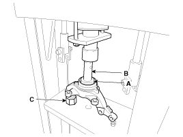
| (1) |
Install the front knuckle assembly (A)
on press. |
| (2) |
Lay a suitable adapter (B) upon the hub
assembly shaft. |
| (3) |
Remove the hub assembly (C) from the
knuckle assembly (A) by using press.
| |
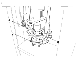
| 3. |
Remove the hub bearing inner race from the hub
assembly.
| (1) |
Install a suitable tool (A) for removing
the hub bearing inner race on the hub
assembly. |
| (2) |
Lay the hub assembly and tool (A) upon a
suitable adapter (B). |
| (3) |
Lay a suitable adapter (C) upon the hub
assembly shaft. |
| (4) |
Remove the hub bearing inner race (D)
from the hub assembly by using press.
| |
| 4. |
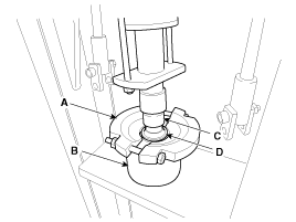
Remove the hub bearing outer race from the
knuckle assembly.
| (1) |
Lay the hub assembly (A) upon a suitable
adapter (B). |
| (2) |
Lay a suitable adapter (C) upon the hub
bearing outer race. |
| (3) |
Remove the hub bearing outer race from
the knuckle assembly by using press.
| |
| 5. |
Replace hub bearing with a new
one. |
| 1. |
Install the hub bearing to the knuckle
assembly.
| (1) |
Lay the knuckle assembly (A) on
press. |
| (2) |
Lay a new hub bearing upon the knuckle
assembly (A). |
| (3) |
Lay a suitable adapter (B) upon the hub
bearing. |
| (4) |
Install the hub bearing to the knuckle
assembly by using press.
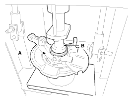
| - |
Do not press against the
inner race of the hub bearing because that can
cause damage to the bearing
assembly. |
| - |
Always use a new wheel
bearing
assembly. | | | |
| 2. |
Install the hub assembly to the knuckle
assembly.
| (1) |
Lay the hub assembly (A) upon a suitable
adapter (C). |
| (2) |
Lay the knuckle assembly (B) upon the
hub assembly (A). |
| (3) |
Lay a suitable adapter (C) upon the hub
bearing. |
| (4) |
Install the hub assembly (A) to the
knuckle assembly (B) by using press.
|
Do not press against the inner
race of the hub bearing because that can cause damage to
the bearing
assembly. | | |
| 3. |
Install the snap ring (A).
|
| 1. |
Check the hub for cracks and the splines for
wear. |
| 2. |
Check the brake disc for scoring and
damage. |
| 3. |
Check the knuckle for
cracks. | |