| 1. |
Remove the engine cover.
|
| 2. |
Disconnect the battery negative
terminal. |
| 3. |
Remove the air clean hose.
(Refer to Intake and Exhaust System - "Ari
Cleaner") |
| 4. |
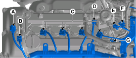
Disconnect the engine wiring connector and
haness clamp and then remove the cylinder head protector and wiring
from engine.
| A. |
Turbo charger solenoid valve
connector |
| B. |
Exhuast OCV(Oil Control Valve)
connector |
| C. |
Ignition connector #
1,2,3,4 |
| D. |
FPCV(Fuel Pressure Control Valve)
connector |
| F. |
Exhuast CMPS(Cam position Sensor)
connector |
| G. |
Intake CMPS(Cam Positoin Sensor)
connector
|
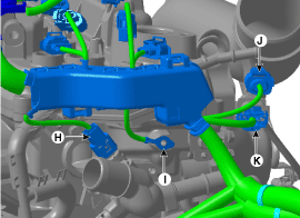
| H. |
WTS(Water Temperature Sensor)
connector |
| J. |
Front Oxygen Sensor
connector |
| K. |
Front Oxygen Sensor
connector
| |
| 5. |
Disconnect the exhaust OCV(Oil Control Valve)
connector.
(Refer to Fuel System - "CVVT Oil Control
Valve") |
| 6. |
Disconnect the ignition coil.
(Refer to Engine Electrical System - "Ignition
Coil") |
| 7. |
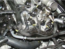
Remove the PCV(Positiv Crankcase Ventilation)
hose(A).
|
| 8. |
Remove the high pressure fuel
pump.
(Refer to Fuel System - "High Pressure Fuel
Pump") |
| 9. |
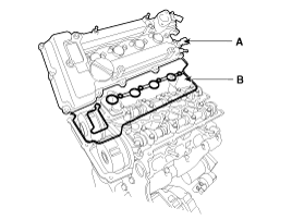
Remove the cylinder head cover(A),
gasket(B).
|
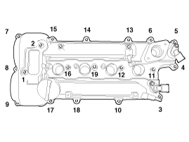
Loosen the cylinder head cover bolts
with the order and steps. |
|
| 1. |
Install the cylinder head cover.
| (1) |
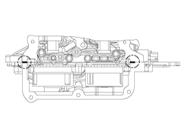
The hardening sealant located on the
upper area between timing chain cover and cylinder head should
be removed before assembling cylinder head
cover. |
| (2) |
After applying sealant, it should be
assembled within 5 minutes.
Bead
width : 2.0 ~ 3.0mm(0.07 ~0.11
in.)
Sealant
: LOCTITE
5900H
|
|
| (3) |
Install the cylinder head cover (A) with
a new gasket (B).

|
Do not reuse the disassembled
gasket. | |
| (4) |
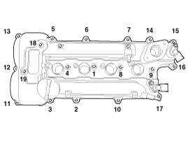
Tighten the cylinder head cover bolts
with the order and steps.
Tightening torque
1st step:
3.9 ~ 5.9 N.m (0.4 ~ 0.6 kgf.m,
2.9 ~ 4.3 lb-ft)
2nd step: 7.8 ~ 9.8 N.m (0.8 ~ 1.0
kgf.m, 5.8 ~ 7.2 lb-ft)
|
| |
| 2. |
Install in the reverse order of removal.
| |